Before powering up the system or doing anything else, I want to see what condition the power supply is in. The importance of the power supply is obvious: without it functioning properly, the condition of anything else in the system is a moot point. Not only do we need the appropriate voltages, we need them to be stable and clean. “Clean” meaning with as little voltage ripple and noise as possible. A power supply in a computer is responsible for generating a handful of different voltages, mostly positive but also some negative, that need to be as stable as possible to ensure the proper operation of everything else in the system.
Why is this important? When DC voltages fluctuate, this can stress components like capacitors and can introduce errors in digital circuits. Of course, no power supply is perfect and there is always some ripple and always some noise. In fact, the ATX specification actually has an acceptable range of ripple for each voltage rail that an ATX-compatible power supply supplies. We’ll be taking a closer look into this later on.
Made by “Dell”
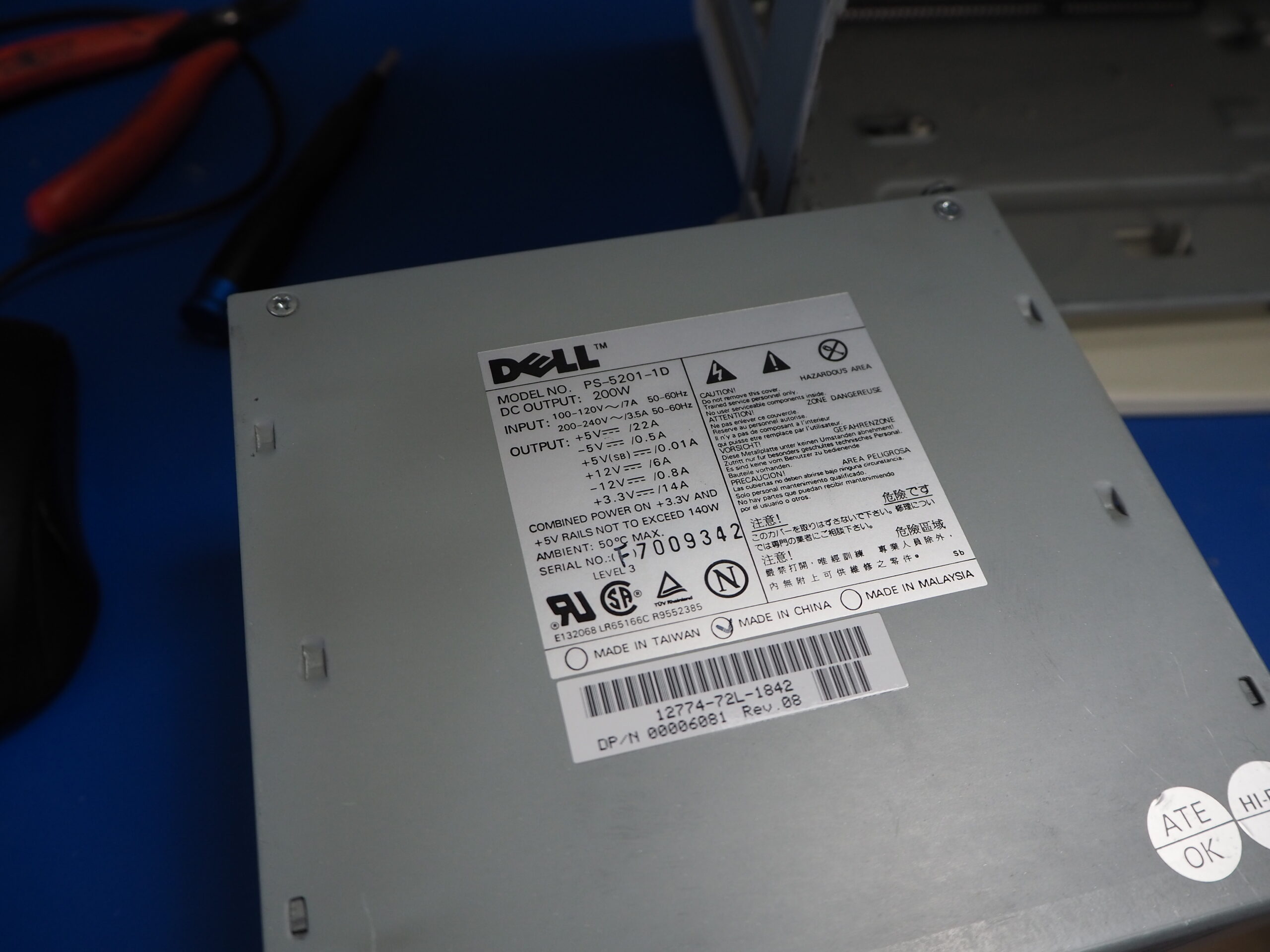
The power supply in the Pro200n is the original. The model number is PS-5201-1D and the Dell part number is 00006081. Even though it sports a Dell logo, Dell did not (and maybe still does not?) manufacture power supplies. There were a handful of popular power supply manufacturers during this era for OEMs with one being Lite-On.
When I was doing some research on this model, I found several references to Lite-On PS-5201-## models, including a photo of one:
I also found references to Compaq, HP, Lenovo, and so on PS-5201 models. It seems likely that Lite-On licensed this model to PC manufacturers, and could customize it for them as needed.
The proprietary scourge
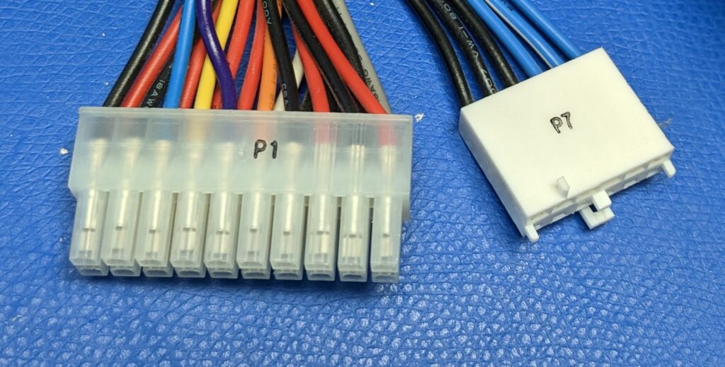
In Dell’s case, they opted for a proprietary layout for the motherboard power. So while this power supply is physically the same size as any other standard ATX supply, it differs in that the +3.3V outputs are located on a separate AT-style connector instead of on the main 20-pin ATX connector:
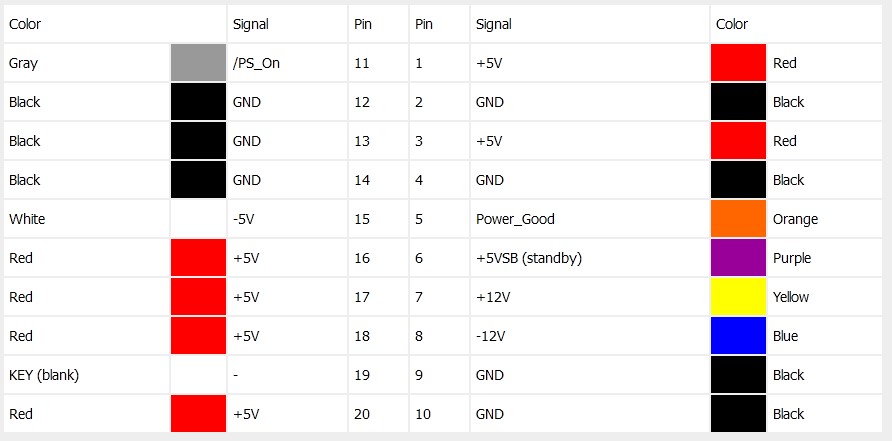
Here’s the 20-pin ATX connector (P1 above) pinout from pinouts.ru:
The P7 connector houses the +3.3V outputs along with 3 corresponding grounds.
A standard 20-pin ATX connector has three +3.3V outputs and 7 total grounds, whereas the Dell scheme has 10 total ground connections: 7 on the ATX and 3 on the 6-pin AT connector. We’ll need to delve into this deeper to see if there was any technical reason for this, or if they simply took a page out of Apple’s playbook and were attempting to force users to buy specific power supplies (ideally through Dell, I’m sure).
What’s the impact of this change? You cannot use this Dell supply in a standard ATX system without an adapter, nor can you use a standard ATX supply in any model Dell that uses this scheme. Doing so would lead to damage to the motherboard, the power supply, or maybe both.
Specifications
Here are the specifications of the power supply:
| Model number | PS-5201-1D Rev. 08 |
| DC OUTPUT | 200W |
| AC INPUT | |
| 100-120V | 7A 50-60Hz |
| 200-240V | 3.5A 50-60Hz |
| DC OUTPUT | |
| +5V | 22A |
| -5V | 0.5A |
| +5Vsb | 0.01A |
| +12V | 6A |
| -12V | 0.8A |
| +3.3V | 14A |
| Combined power on +3.3V and +5V rails not to exceed 140W | |
| Max ambient temperature | 50°C |
The revision of this model is “08” and after doing a little searching, the earliest I could find was listed as “02.” The latest I found was “L10.”
Interestingly, most of the other “PS-5201” models I’ve seen do not allow for as high of combined power on the +5V and +3.3V rails as the Dell supply does. This is likely due to manufacturers specifying certain requirements to Lite-On, and different revisions reflecting those requirements and as component availability changes.
Visual inspection
Before doing anything else, I went ahead and disassembled the power supply to make sure there was no obvious physical damage.
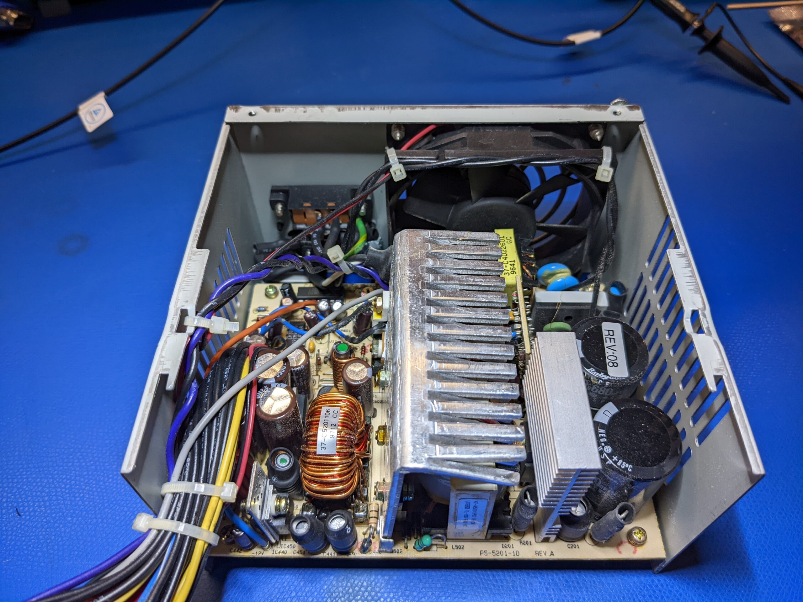
Nothing out of the ordinary, and it looks like any other ATX power supply from the era. We’ll go through and understand more about each section of the supply and how it works later on. What’s important now is that everything visually looks intact. I don’t see any obvious capacitor leakage or bulging and no burn marks on components or the PCB.
I did see a revision marking on the PCB:
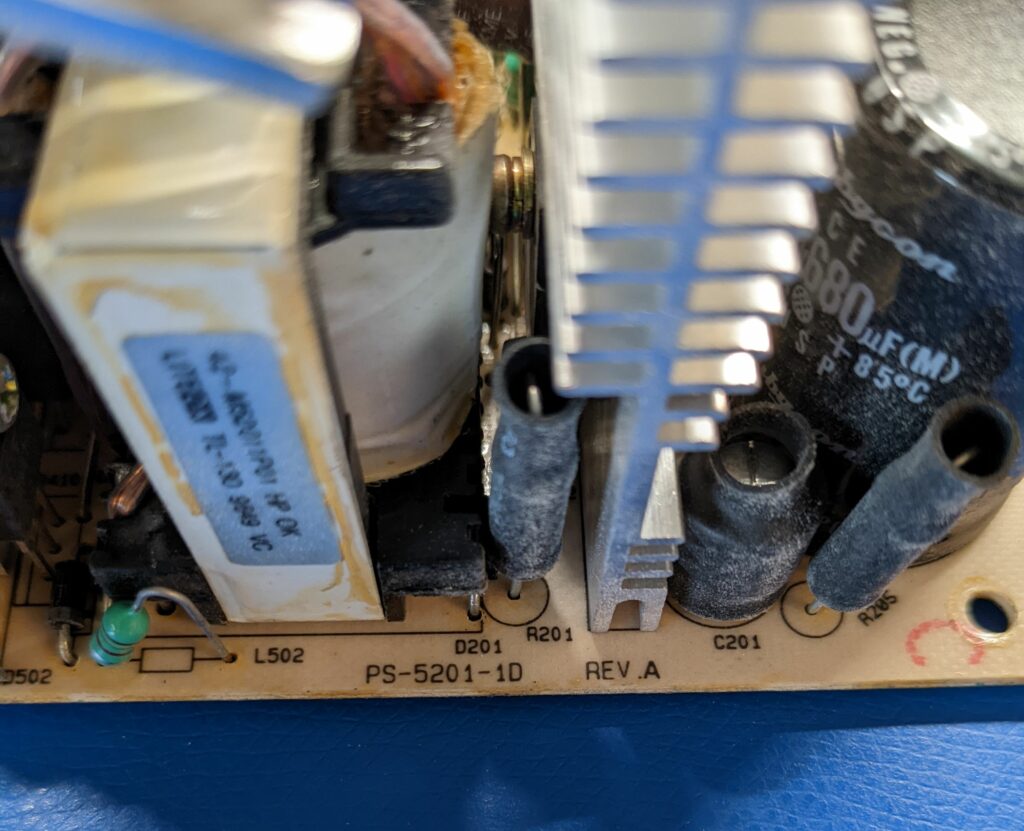
I suppose that means this is the first iteration of the model 1D PS-5201? The exterior label indicates revision 08, so maybe this means that earlier revisions all used the same internal PCB?
Is it safe to turn on?
Since we verified that everything looks visually intact, we should now see if some key components are electrically intact.
We’ll first see if the input rectifier is intact. This converts the incoming AC voltage to an unregulated DC voltage. Full-wave rectifiers like the one in this power supply are simply four diodes in a bridge configuration, and they are generally in one integrated component rather than four discrete diodes.
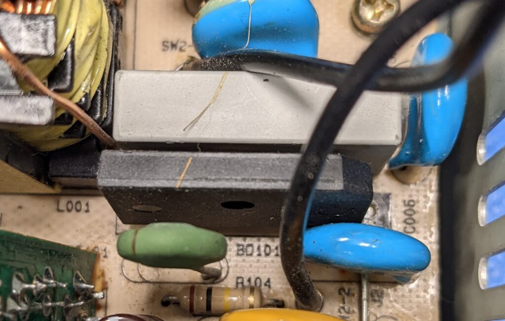
Component BD101 is the bridge rectifier. Because these are essentially just diodes, we can test these using a multimeter in diode mode. We should read a normal diode drop from each AC input to the positive output, and no connection from each AC input to the negative output.
That’s exactly what I found: a ~0.5V drop from AC to + and an open line from AC to -.
So our bridge is good according to our basic test. Let’s now take a look at our main filter capacitors. These ensure that our rectified DC voltage is smoothed to be as consistent as possible. Because this is a switch-mode supply, we are dealing with very high DC voltage at this stage of the circuit. If we take our standard line voltage here in the USA, we should be seeing (120V * 1.414) = ~170VDC. These capacitors have to be stout and capable of handling this high voltage. In the photo of the power supply with the cover removed, they are the large black cylinders in the bottom right.
Right now, all I want to do is make sure they are actually working as capacitors. We’ll recheck them in depth later on, but let’s simply set the multimeter to resistance mode, and see if we get an increasing resistance as the capacitor charges.
Each capacitor started out at 0 Ω (an uncharged capacitor is basically a dead short) and then quickly increased to over 5 kΩ. This tells me that the capacitors were indeed storing a charge, so at the most basic level, they are working and are not shorted (the important part).
There’s also a fuse near the +5V standby transformer that I tested, which was intact and not blown.
With those results in mind, we can try turning on the supply. There are many, many more components that could cause problems, but we know at least that the initial high voltage components are okay and this is about the extent of what we can do with a multimeter and not removing any components. Additionally, if this were even older (let’s say from the 1980s or earlier), we’d want to do even more to ensure it was safe to power up, but not applicable here.
Turning it on
Unlike older AT supplies, ATX power supplies do not use a power switch connected to the incoming AC. Instead, they use a standby circuit which waits for a signal from the motherboard (which in turn is signaled by the actual power switch) to power up. This standby circuit is constantly energized as long as the power supply is connected to AC power, and it outputs a +5V signal to the PS_ON pin of the main ATX connector (see pinout diagram above). When this signal is brought low to ground, the standby circuit then commands the rest of the power supply to start. You can read more about this on page 17 of the ATX power supply design guide.
Since the supply is out of the PC, we’ll instead use a jumper wire to connect the PS_ON output to a ground. This is a short, but that’s okay because there is an internal pull-up resistor that limits current.
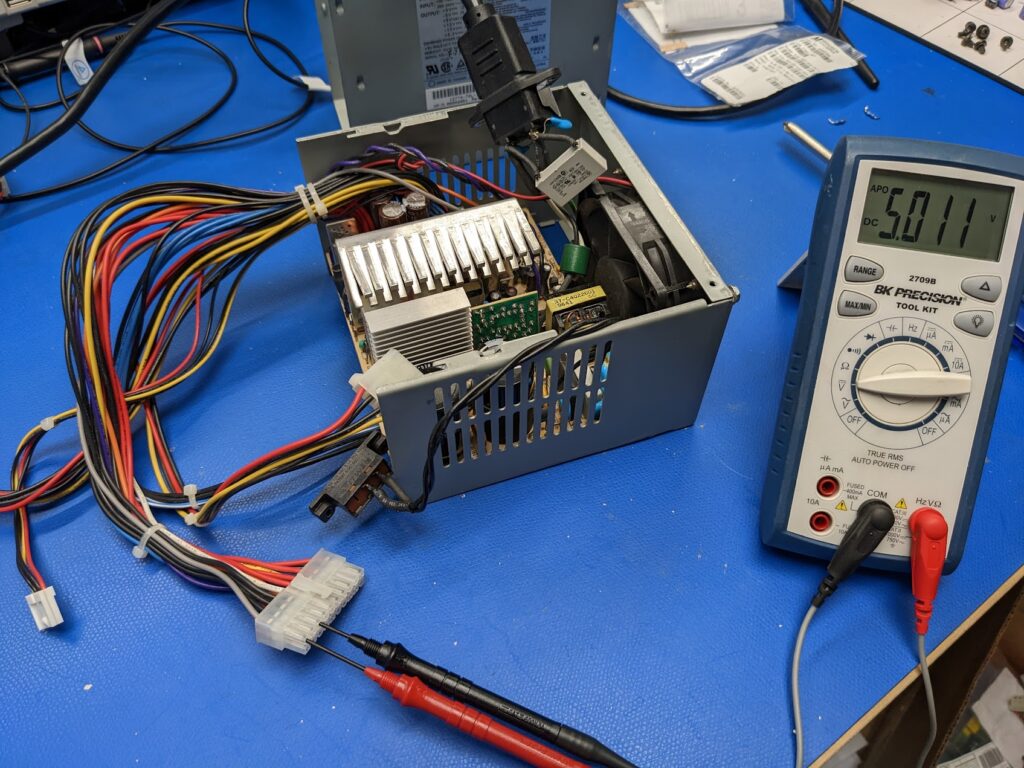
But first, I checked to make sure that we had +5V output on the PS_ON pin:
The last step before power-up is to connect some sort of load. Switch-mode supplies in general do not operate well without a load of some type, though some can if designed that way. This is acceptable according to the ATX spec (section 3.5.3).
For this, I’ll simply use a resistor to provide a load on the +5V rail. I’m using an 8 Ω 50W resistor which draws 0.63A or around 3W.
I’ll monitor the +12V output with the multimeter to make sure we’ve got voltage output.
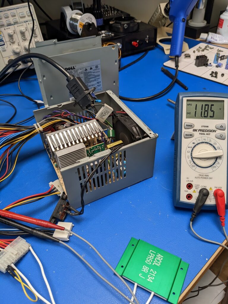
The power supply started up, and I measured +11.85V on the +12V rail. This is obviously low, but not alarming as we have such a light load on the supply. Once the power supply is driving a normal load, this regulation should improve.
Now that we’ve gotten to this point, we will move onto the testing…