The problem
My Brother HL-L2360DW laser printer went into a reboot loop after a power outage. The LCD initializes and displays solid blocks, followed by a blank screen, and the Wifi button LED blinks once, and then the cycle repeats. Holding the “GO” button either during startup or while it’s looping puts the printer into “Users Mode” which displayed on the LCD. The service manual for this particular model does not mention this mode, but I found another service manual that did. I tried every possible option, but always ended up in the same place.
I removed the access panels on the printer and quickly checked voltages from the low-voltage power supply. I didn’t suspect a problem here, and I didn’t find one… all the voltages measured OK, but that’s always the first step. I then turned to the main PCB (p/n B512386-4) as the issue was almost definitely there. I tried disconnecting all external connections: the HV power supply, laser unit, motor, etc but this had no effect on the issue.
The service manual has a simplified block diagram showing the main PCB components and their connections. There is a Renasas ARM MPU in a 144-pin QFP package that serves as the main controller. This is powered by a 3.3V rail that is generated by a DC-DC converter. This voltage checked OK, as expected. The MPU uses I2C to communicate with an EEPROM as well as an IC which is labeled “HYPNOS” in the diagram. Among other things, the HYPNOS appears to be responsible for sending the AC zero crossing signal to the MPU which is probably for controlling a triac or SCR. I checked the SCL and SDA lines on my scope, and confirmed that the MPU is sending clock as well as data. Entering into “Users Mode” immediately ceases I2C communication, and it doesn’t begin again until the machine cycles.
The MPU also uses SPI to communicate with a serial flash IC (a cFeon QH64) labeled U7 on the board, which is likely used for the firmware. I was able to see SPI clock and data on the scope, so it seemed like the main MPU was intact.
I don’t think the EEPROM (a ST M24C32-W) stores anything absolutely necessary for startup and some of the parameters can actually be set in a maintenance mode according to the service manual. There are also a number of error codes related to EEPROM, DRAM, and flash ROM failure. I haven’t received any error codes, though. At this point I was thinking that the firmware was most likely corrupted given the behavior of the system.
I knew I would need a replacement board due to the current state of repair parts and software availability. I was unable to find an exact replacement board, but I was able to find a board for a Dell E310DW which is essentially a re-badged HL-L2360DW. The part number for the board differs by one digit (B512386-5), and it visually looks identical.
Since a replacement was on the way, I decided to go a bit further to see if I could figure out exactly what was at fault. I desoldered the EEPROM (U1) and there was no change in the behavior. I desoldered the QH64 flash IC (U7), and bam– no output on the LCD. Does this mean that the firmware is actually intact and that the issue is with the EEPROM? I soldered the QH64 back in, and was back to where I started. Observing the I2C and SPI lines, it is clear that the system is simply looping. It attempts to boot, something fails, it restarts, repeat.
Interestingly, the previously mentioned HYPNOS has an output pin labeled “CPURST” as in “CPU reset.” There were several ICs on the board that I was unable to find any datasheets for, so at first I wasn’t sure exactly which one was the HYPNOS. The block diagram showed 7 pinouts, one of which was tied to the AC signal for the zero crossing detection. I was able to trace the pin header for the AC signal from the power supply, and eventually found a 20-pin SMD that looked like it might be the one. I probed around with the scope, and found I2C communication on one of the pins, so I’m fairly confident it was the right one. The IC itself is labeled “510A” with “DN5” on the second line, but otherwise no other identification. I desoldered it, and the system would not boot, so nothing gained there.
The repair
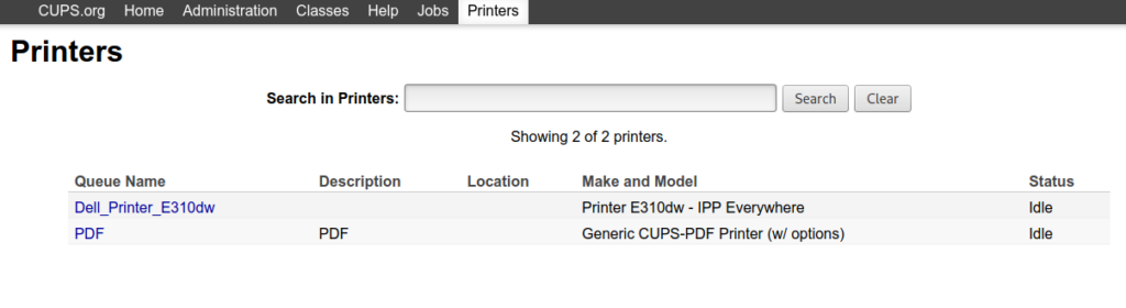
I received and installed the replacement board, and the printer is back up and running, albeit as a Dell now:
This at least confirmed what I already knew. The printer was intact other than something on the main PCB. On closer inspection, the Dell board is not quite identical to the Brother, as the flash IC is different. It is a GigaDevice 25Q64CSIG and there is a 10k pull-up resistor on the CS pin which is absent on the original board. The EEPROM is different as well. This new board uses a slower SPI clock at 25MHz, compared to 50MHz for the QH64. I’m thinking that the Dell board might be a slightly newer revision given the part number. I wonder if Brother had issues with the older design given they left CS floating.
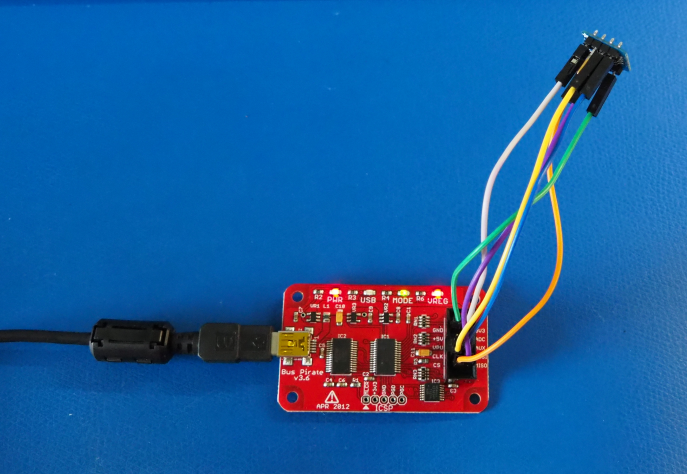
I de-soldered the flash IC and whacked it onto a breakout board. I hooked it up to a Bus Pirate:
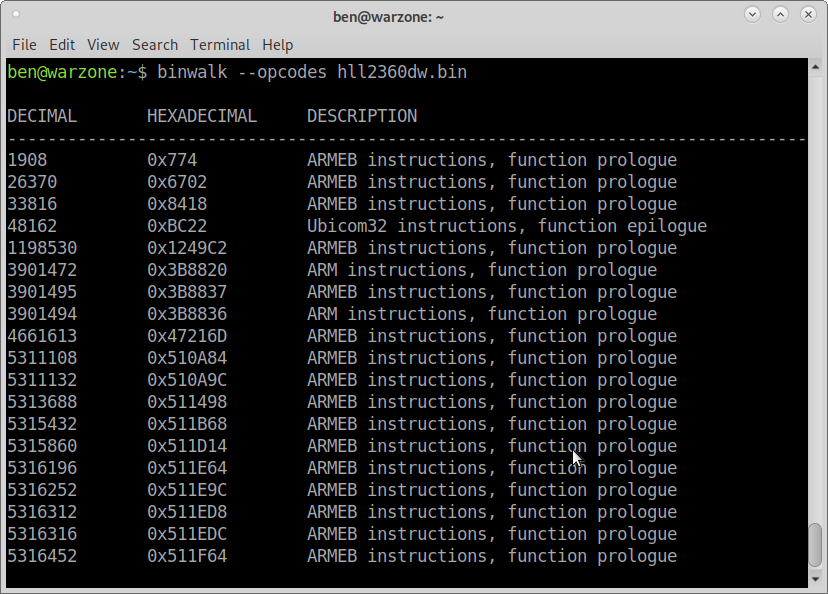
I used spiflash to extract a .bin of the firmware. binwalk showed that the firmware consists of ARMEB instructions, which is ARM’s “old” application binary interface (ABI) that uses big-endian:
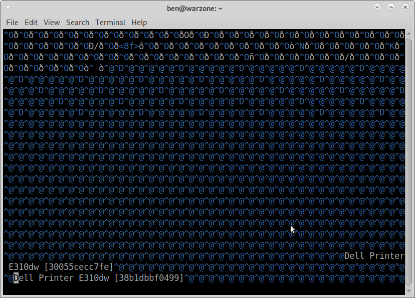
strings output showed an entry for “Users Mode” so it appears that this is indeed part of the firmware. Hmm… does this mean the firmware was actually intact all along? For grins and giggles, I also found entries for “Dell Printer E310dw.” I suppose I could change the name of the printer back to the original Brother model if I wanted… or something entirely custom!
I went ahead and wrote the .bin from the Q64 from the Dell board to the QH64 from the Brother board.
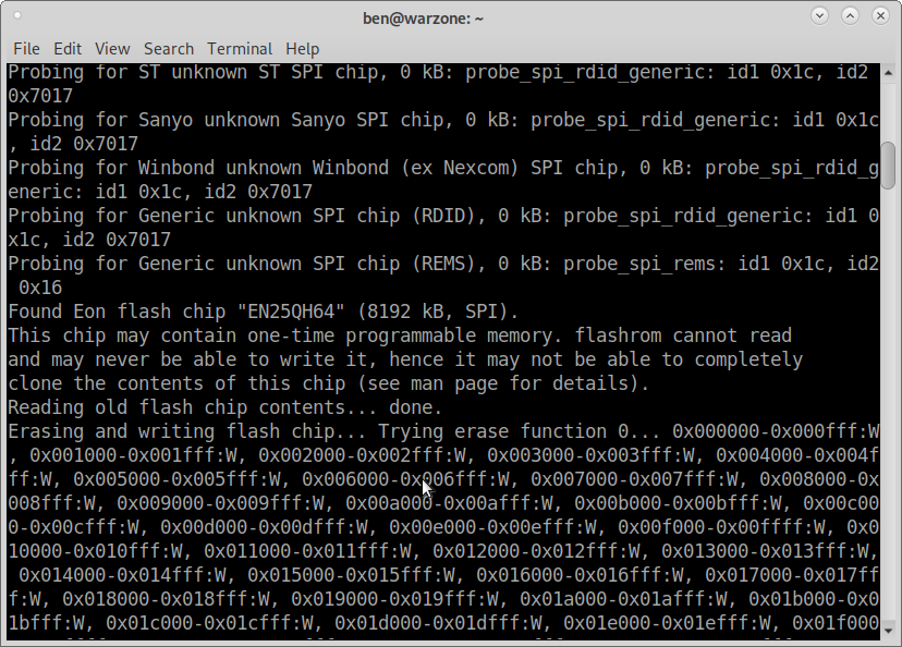
That completed successfully, so I re-soldered the QH64 back onto the original Brother board. I reinstalled the board and turned it on.
Success! Sort of…
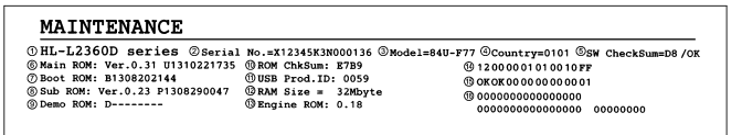
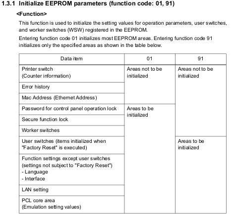
The printer booted into maintenance mode. I checked the service manual for the different commands, and printed a test page using command “09”. It worked! With that success, I chose command “01” which automatically set the EEPROM parameters. I then printed a “maintenance information” report using command “77” which confirmed that this Dell firmware is indeed at least newer than the version shown in the service manual:
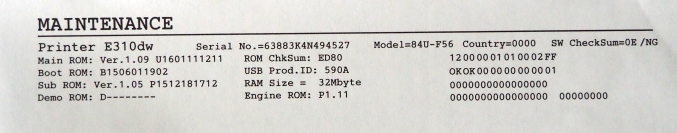
The “SW CheckSum” shows “NG” which I assume means “not good,” but I’m not sure what this really indicates or what it is calculating a checksum for. After exiting maintenance mode, everything seemed okay. Unfortunately, I then noticed there was no network option in the main menu, and the Wifi button did not respond.
The board uses a Realtek PHY, and after checking the IO line to the MCU, it was clear that something was going awry and the MCU was choosing to shut down the PHY. I went back into maintenance mode and selected option “80” which displays machine log information including the MAC address. No MAC address was listed, so that was almost definitely the issue.
The service manual indicated that the MAC address is stored on the EEPROM, but it is not an initialized parameter. In other words, it is pre-defined on the EEPROM and there’s no way to update or change it from the printer itself:
So, I de-soldered the EEPROM again in hopes of seeing if I could either manually edit the MAC address, or perhaps dump the contents of the Dell board EEPROM onto this one. During this process, the original EEPROM died. It developed an internal short which killed the chip when I was trying to read it. I probably exposed it to too much handling and heat.
I slapped the Dell board back in and the printer (and networking) works fine of course. At some point I may order another EEPROM IC and try the above read & write sequence. For now though, I’m done with this project and mostly accomplished what I set out to do: repair the printer, and determine what went wrong with the original. I think both the firmware and EEPROM were corrupted during the power loss / surge event.